USB: The Universal Serial Bus: ATTINY2313
Last Updated: 23 Sept 2012
Appendix Q is now available
My Blog
Featured at:
www.hackaday.com
Don't throw away your old electronic devices
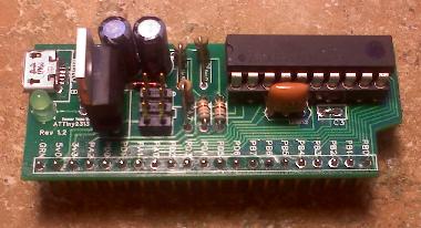
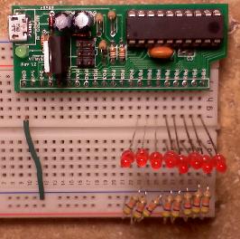
On this page, I will show how to make a small USB device, program it, then using the information in my book, you could then communicate with the device. See Appendix Q for more detailed information.
Since the idea is not to teach you the electrical hardware of the USB, but to teach the software side, this tutorial will create a small, USB device that simply allows you to attach to a bread board and add components so that you can then create your own devices to run other components, make small robots, etc.
Here is an image of the finished device. The image on the left is the completed board while the image on the right is the device attached to a bread board.

The following is a list of parts you will need to create and use this device:
| Count |
Item |
Description |
Link |
Each |
| 1 |
The Programmer1
Used to program the ATTiny2313A.
(Either one of the following two -->) |
"commercially available" See here for assembly instructions. |
www.adafruit.com |
$22.00 or $15.652 |
| Smaller, simple, less parts, easier to assemble. |
Available Here |
| 1 |
The PCB |
Our device's board. |
Available Here |
7.50 |
| 1 |
USB Type B Micro |
MICRO_B |
Mouser |
1.14 |
| 1 |
Green LED |
LED1 |
Mouser |
0.08 |
| 1 |
Six pin Header (2 * 3) |
HDR |
Mouser |
0.67 |
| 2 |
5.1v Zener Diode |
D1, D2 |
Mouser |
0.07 |
| 1 |
82 Ohm resistor |
R6 |
Mouser |
0.29 |
| 1 |
1meg Ohm resistor |
R2 |
Mouser |
0.29 |
| 1 |
1.5k Ohm resistor |
R1 |
Mouser |
0.29 |
| 1 |
4.7k Ohm resistor |
R5 |
Mouser |
0.29 |
| 2 |
68 Ohm resistor |
R3, R4 |
Mouser |
0.15 |
| 2 |
10uF capacitor |
C1, C2 |
Mouser |
0.35 |
| 1 |
regulator |
TO-220 (LD1086) |
Mouser |
0.95 |
| 1 |
12 Mhz Resonator |
12 Mhz |
Mouser |
0.50 |
| 1 |
36 pin header |
|
Mouser |
0.83 |
| 1 |
ATTiny2313A 20 pin |
2313 |
Mouser |
1.31 |
| 1 |
20 pin Socket (Optional) |
|
Mouser |
0.69 |
| Total Cost:3 |
Adafruit Programmer: |
$37.97 |
| fysnet.net Programmer: |
$31.62 |
1Please note that you only need to purchase "The Programmer" once. You can use it multiple times and on multiple projects.
2Includes the cost of the 6-pin cable connector, available here, not included in the kit from fysnet.net.
3Cost in US Dollars at time this list was created. Does not include any shipping and handling that may apply to any order.
The PCB
Once you have received your Programmer, PCB, and components, you can get started soldering them to the board.
A tip for soldering: Get a good solder paste and place a small dab on the part you are soldering. Place a small amount of solder to the tip of you iron. Then touch the tip of the iron to the part (pin) you want to solder. As soon as the pin is warm enough, the solder will flow to the pin. Hold the iron on the pin for a split second longer, then remove the iron. Be sure to hold the iron on the pin and the PCB's solder pad at the same time. Holding the iron on just the pin, might not make the PCB's solder pad warm enough to get a good connection. Don't hold the iron on the components pin for very long, you may damage the component. If the component is not taking the solder, you didn't put enough solder paste on the pin. Try again.
- First, start with the USB connector. You may need to "adjust" the mounting pins on the connector to get it to fit just right. Once you have the connector snug to the board, make sure to solder the mounting pins tightly to the board using plenty of solder. Then solder the 5 data pins. They may be difficult to reach, but if you put enough paste on them and the board, you can run your "loaded" iron across them a few times and the solder will take just fine.
- Solder LED1 and R6 just below the USB connector. These two components simply show that there is 5.0v to the board. Remember that LED's are polarized. The long pin on the LED must be toward the VCC side with the short pin toward the resistor.
- Solder D1 and D2 to the board. These two diodes make sure that if you happen to have the device plugged in and the programmer plugged into it, you don't "contaminate" each other.
- Solder TO-220, C1, and C2 to the board. These components are used to drop the voltage from the USB's 5v0 to the controllers 3v3 needed. The TO-220 is a voltage regulator and needs a capacitor on the 5v0 side and another on the 3v3 side. Remember that these capacitors are polarized. The side of the capacitor should have a line on it for the negative side.
- Solder the 6-pin HDR to the board. This header is used by the programmer to program the controller. When connecting the 6-pin cable for programming, make sure that the ribbon is comming from the TO-220 side. Connect the 6pin cable to the programmer so that the keyway matches the silk picture underneath the 6 pin header. There should be a small circle on the top right corner of the silk. This indicates the red line should be on top, for the top left pin. When plugging the cable to the header, the red line should also be on top.
- Solder R1 and R2 to the board. These two resistors are the pull-up resistors for the USB data lines. Be sure not to get the two resistors mixed up. The right one should be the 1Meg and the left will be the 1k5 (1.5k) resistor. These resistors must be placed "standing" due to room restraints. Remember that resistors are not polarized. They have no negative or positive direction.
- Solder R5 to the board. This is used with the Reset pin on the controller. If the reset pin goes low (no power), the board is in reset. This resistor holds the Reset pin high.
- Solder R3 and R4 to the board. These are the data lines to the controller. (If you use the www.mouser.com part number above, these resistors are small and can lay flat on the board)
- Solder the 12Mhz Resinator to the board. This component is not polarized. You may place it either way on the board.
- Now solder the (optional) 20 pin socket to the board. If you choose not to use the socket, solder the controller to the board. However, please note that with the socket, you can remove the controller if you ever damage it in some way, or choose to use another 20 pin controller. If you solder the controller directly to the board, be sure not to hold the iron on the controller's pins for very long.
- Lastly, break off 21 pins of the 36 pin header and solder it to the board. I left a slight angle to the pins.
If you soldered everything correctly, held enough heat to the pins, but not too much, and used plenty of solder paste, your PCB should now be ready to program.
The Programmer:
You can get the programmer from one of the URL's listed above in the parts list. If you get the kit from www.adafruit.com, you will need to solder all of the components onto it as well. Be sure to see the instructions listed at the URL above. If you get the kit from www.fysnet.net, you can request it be unassembled or assembled at no additional cost. If you already have a programmer, then you don't need to purchase another one.
The programmer needs to be installed on your host machine. I use WinXP and the driver for it found here, specifically Windows USBtinyISP driver for WinXP 32-bit. For now, you don't need any other files on that page (if you are using WinXP as your host.)
Install the driver (before you plug your programmer in), then plug in the programmer. If all went well, the Windows task bar should show prompts stating so and the programmer's green LED will be lit.
If you have the www.adafruit.com program and follow the MakeIt link, here are a few notes:
- When you solder the 100uf capacitor on the board, be sure to solder it high enough off of the board so that you can bend it over the chip without pulling the leads out of the capacitor.
- The picture/instruction where it says to install jumpers instead of resistors for R4 and R7; I did not install jumpers, I installed the resistors and have had no problems.
- The last picture/instruction before the Make 6-pin cable section can be ignored if you ordered the programmer from the list above.
- The programmer from the URL above, at least the one I received, came with the cables already assembled.
- Make sure to leave the jumper "clip" on JP3 on only one pin. i.e.: don't connect the two pins. You will "jump" this jumper just before you are ready to program your device.
Your programmer should now be ready for use.
As a side note, if you have a programmer that uses an ATTiny2313, and that chip some how loses its firmware, you can not reprogram the programmer without another programmer. Therefore, it is my suggestion that you program another 2313 with the firmware from here and store it away for just this purpose.
The Cross Compiler Toolset:
You will need to download and install the cross compiler WinAVR so that you can compile and "burn" your code to the 2313 chip. The one I use is the WinAVR for Windows. If you are using Linux or another host, be sure to find that one.
You will also need the USB library from http://www.obdev.at/products/vusb/download.html.
Have a look at this page for an example of some code you could use.
The Rest of the Story:
Now, using the 8 pins of the controller, you can use your imagination to create your own devices.
You can send more than just single digit control transfers. Using the buffer space, you can now send multi-byte data to the controller as well.
The sky is the limit. You can send a total of 256 different bRequests types each with data in the SETUP packet itself, and/or by the buffer pointed to by the SETUP packet. (note: you will have to add a bit more code to the firmware to retrieve this buffer data).
For example, if you have a stepper motor on pin 4, send a request type of your choosing with a value in the bIndex field of 4 (for pin 4) and a value of 25 in the nLength field. Your firmware code could then take that as step the motor on pin 4, 25 times.
What's coming up:
If you have any questions, please let me know.