 The following is a list of parts you will need to create and use this device:
 Appendix Q is now available
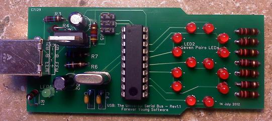
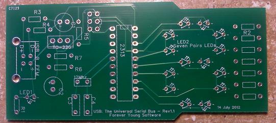
On this page, I will show how to make a small USB device, program it, then using the information in my book, you could then communicate with the device. Have a look here for an updated version. Since the idea is not to teach you the electrical hardware of the USB, but to teach the software side, this tutorial will create a small, mostly useless, USB device that simply allows you to send a single digit, zero through nine, to the device, where as the device will then show that digit. With this knowledge comes the usefulness of this device. You can then create your own devices to run other components, make small robots, etc. Here is an image of the finished device. The image on the left/top is the completed board while the image on the right/bottom is the PCB before any items are attached.
| Count | Item | Description | Link | Average Cost |
| 1 | The Programmer | Used to program the ATTiny2313A. See here for assembly instructions. |
www.adafruit.com | $22.00 |
| 1 | The PCB | Our device's board. | www.BatchPCB.com | 15.00 |
| 1 | USB Type B Female | USB_B_FEM | Newark or Mouser | 0.90 |
| 1 | Six pin Header (2 * 3) | HDR | Newark or Mouser | 0.70 |
| 1 | Green LED | LED1 | Newark or Mouser | 0.25 |
| 14 | Red LED | LED2 | Newark or Mouser | 0.25 |
| 7 | 33 Ohm resistor | R2 | Newark or Mouser | 0.20 |
| 1 | 82 Ohm resistor | R1 | Newark or Mouser | 0.20 |
| 1 | 1meg Ohm resistor | R3 | Newark or Mouser | 0.30 |
| 1 | 1.5k Ohm resistor | R4 | Newark or Mouser | 0.30 |
| 1 | 4.7k Ohm resistor | R5 | Newark or Mouser | 0.30 |
| 2 | 68 Ohm resistor | R6, R7 | Newark or Mouser | 0.25 |
| 2 | 10uF capacitor | C1, C2 | Newark or Mouser | 0.30 |
| 2 | 27pF ceramic capacitor | C3, C4 | Newark or Mouser | 0.20 |
| 1 | regulator | TO-220 | Newark or Mouser | 1.25 |
| 1 | 12 Mhz Crystal | 12 Mhz | Newark or Mouser | 0.30 |
| 1 | ATTiny2313A 20 pin | 2313 | Newark or Mouser | 1.35 |
| 1 | 20 pin Socket (Optional) | Newark or Mouser | 1.45 | |
| Total Cost: | $50.70 | |||
Once you have received your Programmer, PCB, and components, you can get started soldering them to the board.

A tip for soldering:  Get a good solder paste and place a small dab on the part you are soldering.  Place a small amount of solder to the tip of you iron.  Then touch the tip of the iron to the part (pin) you want to solder.  As soon as the pin is warm enough, the solder will flow to the pin.  Hold the iron on the pin for a split second longer, then remove the iron.  Be sure to hold the iron on the pin and the PCB's solder pad at the same time. Holding the iron on just the pin, might not make the PCB's solder pad warm enough to get a good connection. Don't hold the iron on the components pin for very long, you may damage the component.  If the component is not taking the solder, you didn't put enough solder paste on the pin.  Try again.
You can get the programmer from the URL listed above in the parts list.  You will need to solder all of the components onto it as well.  Be sure to see the instructions listed at the URL above.  If you already have a programmer, then you don't need to purchase another one.

The programmer needs to be assembled and installed on your host machine.  I use WinXP and the correct driver to use it for that host found here, specifically Windows USBtinyISP driver for WinXP 32-bit.  For now, you don't need any other files on that page (if you are using WinXP as your host.)

Install the driver (before you plug your programmer in), then plug in the programmer.  If all went well, the Windows task bar should show prompts stating so and the programmer's green LED will be lit.

If you follow the MakeIt link, here are a few notes:
You will need to download and install the cross compiler WinAVR so that you can compile and "burn" your code to the 2313 chip.  The one I use is the WinAVR for Windows.  If you are using Linux or another host, be sure to find that one.

You will also need the USB library from http://www.obdev.at/products/vusb/download.html.

Create a sub-folder for your "figure eight" code and unzip this zip file to that folder.  Within that .zip file is the following firmware code we write to the microcontroller:


#include <avr/io.h>
#include <avr/interrupt.h>
#include <avr/wdt.h>

#include "usbdrv.h"

#define F_CPU 12000000L
#include <util/delay.h>

uchar digits[10] = {
  (1<<PORTB0) | (1<<PORTB1) | (1<<PORTB2) | (1<<PORTB4) | (1<<PORTB5) | (1<<PORTB6), // zero
  (1<<PORTB1) | (1<<PORTB5),                                                         // one
  (1<<PORTB0) | (1<<PORTB2) | (1<<PORTB3) | (1<<PORTB5) | (1<<PORTB6),               // two
  (1<<PORTB0) | (1<<PORTB1) | (1<<PORTB3) | (1<<PORTB5) | (1<<PORTB6),               // three
  (1<<PORTB1) | (1<<PORTB3) | (1<<PORTB4) | (1<<PORTB5),                             // four
  (1<<PORTB0) | (1<<PORTB1) | (1<<PORTB3) | (1<<PORTB4) | (1<<PORTB6),               // five
  (1<<PORTB0) | (1<<PORTB1) | (1<<PORTB2) | (1<<PORTB3) | (1<<PORTB4) | (1<<PORTB6), // six
  (1<<PORTB1) | (1<<PORTB5) | (1<<PORTB6),                                           // seven
  (1<<PORTB0) | (1<<PORTB1) | (1<<PORTB2) | (1<<PORTB3) | (1<<PORTB4) | (1<<PORTB5) | (1<<PORTB6), // eight
  (1<<PORTB1) | (1<<PORTB3) | (1<<PORTB4) | (1<<PORTB5) | (1<<PORTB6),               // nine
};

// this gets called when custom control message is received
USB_PUBLIC uchar usbFunctionSetup(uchar data[8]) {
  usbRequest_t *rq = (void *)data; // cast data to correct type

  if ((rq->bRequest >= 0) && (rq->bRequest <= 9)) { // custom command is in the bRequest field
    PORTB = digits[rq->bRequest]; // turn LEDs on
    return 0;
  } else
    return 0;

  return 0; // should not get here
}

int main() {
  uchar i;

  DDRB = 0x7F; // PB0,1,2,3,4,5,6 as output
  PORTB = 0;

  wdt_enable(WDTO_1S); // enable 1s watchdog timer

  usbInit();

  usbDeviceDisconnect(); // enforce re-enumeration
  for(i = 0; i<250; i++) { // wait 500 ms
    wdt_reset(); // keep the watchdog happy
    _delay_ms(2);
  }
  usbDeviceConnect();

  sei(); // Enable interrupts after re-enumeration

  while(1) {
    wdt_reset(); // keep the watchdog happy
    usbPoll();
  }

  return 0;
}


Now using MAKE.EXE included with WinAVR and the makefile included in the .zip file above, build the above code by typing the following at the DOS Command prompt and hit ENTER:

      make

Please note that the paths within the Makefile file will need to be modified to match your setup.

Now we will need to change the fuse parameters of the chip.  Connect the programmer to the host machine, and connect the two pins of the JP3 jumper using the supplied jumper.  This supplies power to our device.

Please note that this project assumes your programmer will suply our Figure Eight with about +5v0 via the 6 pin cable.  If it only supplies 3v3, you will need to remove the jumper from the programmer and supply 5v0 to the USB connector of the Figure Eight.

Then connect the 6 pin cable to the Figure Eight's 6-pin header and type the following at the DOS Command prompt and hit ENTER:

      make fuse

This will adjust the timing of the chip.

Now we are ready to flash our code to the chip.  Type the following at the DOS Command Prompt and hit ENTER:

      make flash

If all is well, you should see the red LED on the programmer flash, and the status displayed on the screen. You may also see two of the 7 LED segment pairs flash on the Figure Eight.  This is the data being written to the chip.

Please note:  If the flash did not work and you saw some of the LED's on the Figure Eight light up, you needed to program the chip before you soldered the (7) R2 Resistors to the board as described above. If you did not do so, you can cut the right hand side of the two top resistors from the board, reprogram the chip, then solder the leads back into place. (I am working on a revision to bypass this problem).

Once you have a successful flash, you can unplug the programmer from the Figure Eight.
You are now ready to send digits to the Figure-Eight device.  Using the knowledge you gained from my book, send a control request to the device with a value of 0 to 9 for the bRequest byte.

You will see that the Figure-Eight device will now display the digit.
Now, using the 8 pins of the controller, you can use your imagination to create your own devices.

You can send more than just single digit control transfers.  Using the buffer space, you can now send multi-byte data to the controller as well.

The sky is the limit.  You can send a total of 256 different bRequests types each with data in the SETUP packet itself, and/or by the buffer pointed to by the SETUP packet.  (note: you will have to add a bit more code to the firmware to retrieve this buffer data).

For example, if you have a stepper motor on pin 4, send a request type of your choosing with a value in the bIndex field of 4 (for pin 4) and a value of 25 in the nLength field.  Your firmware code could then take that as step the motor on pin 4, 25 times.

I hope you enjoyed this project.  I want to thank this site for the inspiration for doing this project.