A USB to UART COM Serial Port, Part 3

PCB's are back and the components arrived shortly later.

usb2uart0.png

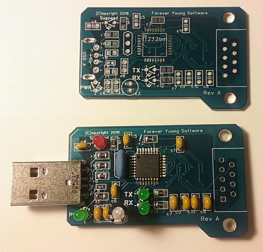
Top is PCB only while the bottom is populated with different types of components, through-hole and surface-mount.

I decided to create the board so that it had all the caps as through-hole and all the resistors as surface mount so that I could try both ways. I am not an expert by any means, but I am not a novice either. The through-hole items were a cinch, but as you can imagine, the surface mount items were a bit more difficult. In fact, the Ferrite Bead was a bit difficult being not but a millimeter in size itself.

usb2uart3.png

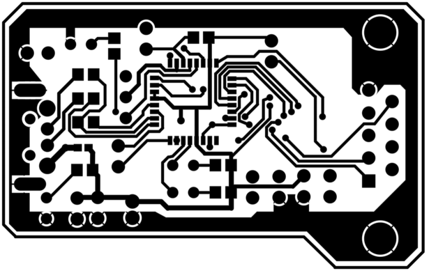
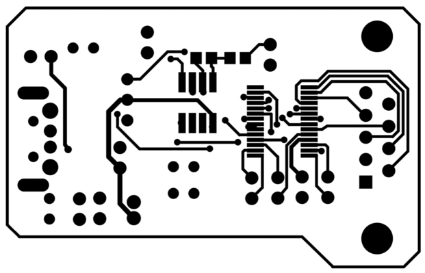
The top side, shown above, has numerous surface-mount items including the FT232. The bottom side, not shown, has two ICs and two resistors, all surface-mount. Surprisingly, the ICs where not that difficult. A little flux, a dab of solder on the iron, and I just drug the tip across the pins, slowly enough to warm them, but not so to "splash" the solder around.

The PCBs were well done and made it a lot simpler than it could have been.


The PCB was ordered from https://www.pcbway.com/ and I am totally impressed. The whole process took about five days from order to delivery. I got five PCB's for five USD plus shipping.

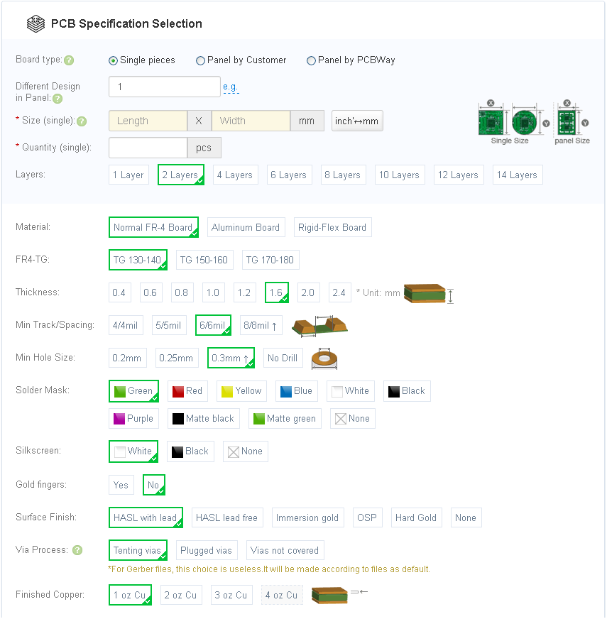
The thing that really impressed me is that this is the only PCB supplier that I know of that allows for this many different options. For example, I could have chosen one of nine solder mask colors as well as thickness of the board. Here is a screen shot of part of the order process.

usb2uart1.png

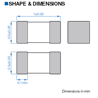
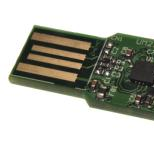
The thickness of the board comes into play if you wish to create a board thick enough to create your own USB connector. For example, I could have done something like the following:

usb2uart2.png


The only thing missing is the DB9 Serial Port connector. I found one via a place in China for $0.18 USD each, but more than $20 USD to ship it. My normal supplier had one for a little bit more, but it was on back order for more than 30 days from now.

I still plugged this board into a laptop and it lit up the LEDs as expected, the red indicating in suspend mode until enumerated.

When I finally get a DB9 connector, I will solder it on and plug in a standard Serial mouse to see if it actually works.

Thank you https://www.pcbway.com/ for doing a great job on the PCBs and for getting them to me so quickly. They exceeded my expectations. Guess whom I will be getting future PCBs from?

If you have any questions or desire the gerber files for this project, please let me know.

A USB to UART COM Serial Port, Part 2

Gerber files created, and sent off to PCB Manufacturer. I am not going to mention which one at the moment, but this new company looks very promising and except for the shipping, which is completely warranted given where they are located, it looks like this company is giving way more options, PCB thickness, etc., and will be my new PCB manufacture source.

Once the PCBs come back, I will be sure to let you know how they did and who they are.

Just for fun, here is an image of the Top and Bottom Copper Gerber files.

top_copper.png bot_copper.png

A USB to UART COM Serial Port

I have decided to get back into electronics for a little while and have decided to make a USB to COM device, giving my laptops, which currently do not have COM ports, access to a regular Serial COM port.

I have drawn up a schematic, next is to create the PCB.

usb2uart.png

Quick (and simple) tutorial on the Bochs Debugger

I have created a quick (and simple) tutorial on the Bochs Debugger. It was created specifically to show a fellow reader to see the advantage of using a good debugger.

It can be found at: https://www.fysnet.net/bochsdbg/index.htm

Debug output in an emulator

A lot of people have asked how to save debug output within their operating system code and/or kernel. For example, during bootup you don't have a file system driver or media device driver loaded yet, so you cannot write to a file. If you are working on your video display code, about the only time you can see text printed to the screen is when you don't need debug output. Also, what if your system is producing a lot of debug strings, so fast that you can't see them on the screen since they are scrolled so quickly?

One of the most effective and easiest forms would be to print them to the printer. Since we are most likely using an emulator, we can print them to a file instead of directly to a printer.

To do this, place a call within your console output routine, probably your putch() routine, a call to kdebugout(ch). The function simply sends the ASCII 8-bit char to the printer either on a parallel port or a serial port. The function below shows this routine written in standard C form and sends the char to the parallel port.

#define TIMEOUT_VAL  256

/* Send the ASCII 8-bit char to the printer */
void kdebugout(bit8u ch) {
   bit8u val;
   int i;
   
   // Wait for the port to be not busy
   // Note: A set bit indicates not busy
   for (i=0; i<TIMEOUT_VAL; i++) {
     val = inpb(0x379);
     if ((val & 0x80) == 0x80)
       break;
   }
   // If the port never became un-busy, just return
   if (i == TIMEOUT_VAL) 
     return;
     
   // Write the 8-bit char to the 8 data pins of the port
   outpb(0x378, ch);

   // Toggle the strobe bit, pausing ever so slightly while it is set
   val = inpb(0x37A);
   val = val | 1;
   outpb(0x37A, val);

   // Note: A smart compiler may optimize this line completely out
   for (i=0; i<TIMEOUT_VAL; i++)
     ;

   // Un-Toggle the strobe bit
   val = inpb(0x37A);
   val = val & 0xFE;
   outpb(0x37A, val);
      
   // Wait for the port to indicate done
   for (i=0; i<TIMEOUT_VAL; i++) {
     val = inpb(0x379);
     if ((val & 0x40) == 0x00)
       break;
   }
   // Note: we ignore the fact that it could never indicate done...
}

The code above should send a single char to the printer fairly quickly since we are using an emulator. i.e.: the emulator's parallel port should always be ready for a char and quickly indicate that it is ready for another.

Now, if you call this routine every time you send a char to the screen, you should also have one sent to the printer. However, since we are using an emulator, for example QEMU, if we indicate to QEMU we wish it to emulate a parallel printer, all chars printed will end up in a text file of our choosing.

For example, the following command line addition will tell QEMU to send all chars to the host system file "para.txt" residing in the current directory:

  -parallel file:para.txt

To do the same for Bochs, use the following line in your bochsrc.txt file:

  parport1: enabled=1, file="para.txt"

Now for the precautions:

  1. If you run your code on real hardware, the code may slow down slightly, waiting for the parallel port to become available.
  2. If you have an actual parallel port with an actual printer attached, you will slow down considerably, and might use a bit of paper.
  3. This assumes the first parallel port. Modify if you need to use a second.
  4. The "para.txt" file is truncated each time you start the emulator, erasing any existing text within the file.

Now for the advantages:

  1. This makes it very simple to save screen output as long as each char you send to the screen, you also send to the printer.
  2. If your emulator supports multiple parallel ports, you can send different stages of debug text to different parallel ports, dividing up the output.

With this idea, most any char you print to the screen, you also print to the "para.txt" file.