5.8. USB Debugger
This debugger implementation is experimental. Please take caution when using it.
usb_debug: type=none|uhci|ohci|ehci|xhci, reset=1, enable=1, start_frame=1, doorbell=1, event=1, data=1, non_exist=1
Currently only none, uhci, or xhci can be specified as the type. Future additions will include the other two controller types.
Only one type may be specified. You can only debug one controller type at a time.
 triggers: (one or more must be specified)
  'reset'       -- When the controller resets a port, the debugger will halt the emulation and display
                   the debugger. This does not include when the HC gets reset, which in turn would reset
                   the downstream ports.
                   The debugger is triggered at the write of the port before the port value is updated by the write.
  'enable'      -- When the controller enables a port, the debugger will halt the emulation and display
                   the debugger. For an EHCI port, the controller automatically enables the port when
                   a high-speed device is detected.
                   The debugger is triggered at the write of the port before the port value is updated by the write.
  'start_frame' -- When the controller starts a new frame, the debugger will halt the emulation
                   and display the debugger. Please note that the implementation of this feature is/will
                   be different with each controller type. Also, if the frame is not active, this trigger will
                   never be called. i.e.: In the UHCI, if the schedule is not in the RUN state, this trigger will
                   not be active.
                -- uhci: Load the next Frame Index and process the TD/Queue pointed by it.
                -- ohci: ** TODO **
                -- ehci: ** TODO **
                -- xhci: Start/Continue to process Transfer Rings.
  'doorbell'    -- When the xHCI controller receives a doorbell ring indicator (for the Command Ring),
                   the debugger will halt the emulation and display the debugger.
                -- When the EHCI controller is to execute a single TD, the debugger will halt the
                   emulation and display the debugger.
                -- When the OHCI controller is to execute a single TD, the debugger will halt the
                   emulation and display the debugger.
                -- When the UHCI controller is to execute a single TD, the debugger will halt the
                   emulation and display the debugger.
  'event'       -- When the xHCI controller posts an event on the event ring, the debugger will
                   halt the emulation and display the debugger. This is only used in the xHCI controller
                   type. Other types will ignore this trigger.
  'data'        -- When the xHCI controller posts an event on the data ring, the debugger will
                   halt the emulation and display the debugger. This is only used in the xHCI controller
                   type. Other types will ignore this trigger.
  'non_exist'   -- When the guest writes to a non-existent port, the debugger will halt the emulation
                   and display the debugger.  This is so you can trigger the debugger via software.
                   Write to the first non-existent port and the debugger will be triggered.
                   Reads have no affect.
The USB Debugger also has a button-bar icon that when clicked will trigger the debugger. However, please note that if the debugger is currently unavailable, due to the controller state for example, the icon will change to squiggly lines and then at the next available controller state, the debugger will display. If the icon has an 'X' through it, the debugger is unavailable.
If you modify any value within the debugger's display, any change that might trigger a change to the controller's state will take place. For example, if you change the Current Connect Status and the Current Enable Status, both will be triggered at the same time by the controller. To keep this from happening, change one and hit the Apply Button. Then trigger the debugger again and change another.
When the Debugger dialog is displayed, you can view/modify different aspects of the controller, the controller root hub ports, as well as other items. For example, with the xHCI debugger, you can view and modify TRBs on the Command Ring. Simply set the 'doorbell' trigger, and when a doorbell is written, the emulation will stop and display the current Command Ring with any available TRBs.
You can turn off or on any trigger (listed above) while within the Debugger dialog. If all of them are off, you can use the Ribbon Trigger button to display the Debugger, then set any triggers active.
The figure below is an example of an xHCI controller using the Doorbell trigger to stop when the Controller receives a TRB in the Command Ring with the Command Ring Doorbell being triggered.
The three register sets are displayed allowing you to modify their values. Please note that modifying the Capability Register set will produce undefined results. It is recommended that you do not modify this register set.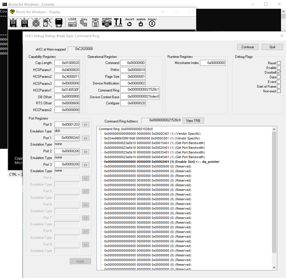
The Debug Flags box allows you to set or clear a trigger. If the checkbox is checked, the trigger is active.
The Port Register set displays the used registers allowing you to modify them as you see fit. Again, undefined results may happen if you modify these registers.
The Tree List shows the current TRB list of the Command Ring. Notice that six TRBs have already been executed. (You should have had the Debugger triggered six times already). The TRB listed in bold is the current TRB to be executed. If you select that item and then click the "View TRB" button, you can modify the TRB before the controller has a chance to execute it. Note that you cannot change the TRB's type, though you can modify its attributes.
The "Continue" button will exit the debugger and continue the emulation. The "Quit" button will quit the entire emulation.
5.8.1. USB Debugger: xHCI
Notes on the xHCI USB Debugger will go here.
5.8.2. USB Debugger: EHCI
Notes on the EHCI USB Debugger will go here.
5.8.3. USB Debugger: OHCI
Notes on the OHCI USB Debugger will go here.
5.8.4. USB Debugger: UHCI
When the 'doorbell' trigger is used, the debugger will trigger before the controller processes the TD *and* again after the controller processes the TD. This is so you can see the TD before it is processed, allowing you to make changes, and then see the results. Please note that the *before* and *after* status only effects the currently executing TD. All other TDs have either already been executed or have not yet been executed.
Changing the 'Active' bit before the controller processes the TD is not allowed since the controller has already found the TD active and is processing it. Changing it after the controller has processed it is allowed, but why would you?
Changing any items in a TD *after* the TD has been processed is not recommended and undefined results may occur.
You normally would not have both the 'start_frame' and 'doorbell' triggers active when using the UHCI. If they are, the 'doorbell' trigger will trigger the first TD in the frame anyway. The 'start_frame' trigger is only used when you want to see the frame's list once at start of frame. The 'doorbell' trigger is used on every active TD found.
If the TD is using BreadthFirst processing, the debugger will not display any TDs linked by the LINK PTR. This is because some drivers point the LINK PTR to itself to make sure the TD is executed. If the TD is executed, the active bit will be clear, so the next TD will be processed anyway.