eMBR partitioning specification 1.05
Version 1.05, last update: 2023 January 11
Copyright © 1984-2025 by Forever Young Software
Permission to make and distribute verbatim copies of this specification, translations of this specification into another language, and derivative works that comment on or otherwise explain it or assist in its implementation, for any purpose and without fee or royalty is hereby granted, provided that the present copyright notice, licensing terms and disclaimer are preserved on all copies.
In addition, the Author covenants not to assert any claims on implementations of this specification, unless such implementations contain derivative work of implementations by the Author, for which specific licensing terms may apply.
THIS SPECIFICATION IS PROVIDED "AS IS," AND THE AUTHOR MAKES NO REPRESENTATIONS OR WARRANTIES, EXPRESS OR IMPLIED, INCLUDING, BUT NOT LIMITED TO, WARRANTIES OF MERCHANTABILITY, FITNESS FOR A PARTICULAR PURPOSE, NON-INFRINGEMENT, OR TITLE; THAT THE CONTENTS OF THIS SPECIFICATION ARE SUITABLE FOR ANY PURPOSE; NOR THAT THE IMPLEMENTATION OF SUCH CONTENTS WILL NOT INFRINGE ANY THIRD PARTY PATENTS, COPYRIGHTS, TRADEMARKS OR OTHER RIGHTS. TO THE FULLEST EXTENT PERMITTED BY APPLICABLE LAW, THE AUTHOR WILL NOT BE LIABLE FOR ANY DIRECT, INDIRECT, SPECIAL, INCIDENTAL OR CONSEQUENTIAL DAMAGES ARISING OUT OF ANY USE OF THIS SPECIFICATION OR THE PERFORMANCE OR IMPLEMENTATION OF THE CONTENTS THEREOF.
No other rights are granted by implication, estoppel or otherwise.
This document describes version 1.05 of the eMBR partitioning system: a free, simple, fully featured disk partitioning system.
The eMBR partitioning system is in the release development stage: this document supersedes any previous version of the specification with no care for backward compatibility.
Since this is a unique partitioning system, and some aspects are still to be defined, suggestions or corrections are welcome, for either the partitioning system or this document. Please contact the author at: fys at fysnet.net. The author wishes to thank those who have submitted comments and criticism in order to improve the eMBR partitioning system.
Table of contents
- Differences from the previous versions
- Definitions
- Binary Multiples
- Structure identification and checksum
- Layout
- Legacy MBR
- eMBR Partition Start
- eMBR Partition Header
- eMBR Partition Entry
- Requirements
- User interface
- Things to consider
Differences from the previous versions
- version 1.05
- Official Release: Official release version 1.05 (2023 January 04)
- limit the code size: Added limits to the
sect_offsetandremainingfields (2023 January 10)
- version 1.04
- Source code fix and added functionality: (2015 Sept 28)
- version 1.03
- Minor clarifications: (2015 Jan 03)
- version 1.02
- Minor clarifications: (2013 Oct 06)
- version 1.01
- Minor clarifications: (2013 June 30)
- version 1.00
- Initial Release: Initial release (2011 June 14)
Definitions
The following terms and conventions will be used throughout this specification:
- must, must not, should, should not, may: these words are to be interpreted as described in RFC 2119;
- reserved for future use: a data field that has not yet been defined. When creating a new entry that field must be written as zeros. When reading an existing entry, a driver must not make assumption about the content of that field. When writing that field to an existing entry, a driver must preserve the value in that field;
- byte: a group of eight adjacent bits, an octet;
- driver: firmware or boot code, or any other part of the operating system, or any application implementing this specification to access an eMBR partitioning system;
- disk: a block device hosting an eMBR partitioning system. This wording is used for simplicity, although that device does not need to be an actual disk memory (e.g. hard disk, memory card, RAM disk). Drivers must limit disk sizes to 264-1 sectors;
- volume/partition: a group of contiguous sectors containing a self-contained file system on a disk;
- sector: an allocation unit, an arbitrary number of bytes, singly accessible, read or written, by a device controlling the media of the disk. This is the smallest number of bytes accessible per physical access of the media, by default usually being a 512-byte sector. This must be a power of two equal to or greater than 512;
- The C++ syntax is used for code snippets and structure formats, with stdint.h integral types. The
chartype is assumed to be 8-bit. Hex numbers are prefixed with0x; - Disk addressing is in the form of Linear Base Addressing, or LBA, and is zero based from the start of the disk. Cylinder/Head/Sector (CHS) addressing is only used in the MBR at LBA 0.
- Unless otherwise stated, all numbers must be stored in little endian format (least significant byte first).
Binary multiples
Table 1 below shows the Binary Multiples and their names which may be used within this specification.
| name | Symbol | Value (Binary) | Value (Decimal, General disk size labels) |
| Kilo | k/K | 210 = 1,024 | 103 = 1,000 |
| Mega | M | 220 = 1,048,576 | 106 = 1,000,000 |
| Giga | G | 230 = 1,073,741,824 | 109 = 1,000,000,000 |
| Tera | T | 240 = 1,099,511,627,776 | 1012 = 1,000,000,000,000 |
| Peta | P | 250 = 1,125,899,906,842,624 | 1015 = 1,000,000,000,000,000 |
| Exa | E | 260 = 1,152,921,504,606,846,976 | 1018 = 1,000,000,000,000,000,000 |
| Zetta | Z | 270 = 1,180,591,620,717,411,303,424 | 1021 = 1,000,000,000,000,000,000,000 |
| Yotta | Y | 280 = 1,208,925,819,614,629,174,706,176 | 1024 = 1,000,000,000,000,000,000,000,000 |
Next would be Ronna then Quetta, but who needs more than 64k of RAM anyway! | |||
Structure identification and checksum
Some structures of the eMBR specification may include a field to make the partitioning system more robust.
A sensitive structure, such as the partition header, may store a checksum field and is computed on a specified block of data. The definition and technique to calculate this checksum is defined by the official CRC-32 standard. The checksum must be recomputed at least every time a sensitive structure or data area is written back to disk.
The following functions show how to calculate the checksum. The data parameter is a pointer to the data area to be checked. The size parameter is the size in bytes of the structure pointed to by data. A driver must initialize the crc32_table once before calling any of the remaining routines. A call to crc32_initialize() may be used.
Please note that the checksum field in the partition header must not be included in the checksum calculation. Initially setting this field to zero will allow it to be a part of the check.
/* Predefined polynomial */
#define CRC32_POLYNOMIAL 0x04C11DB7

/* Lookup table. Must be pre-initialized. */
uint32_t crc32_table[256];

/* Initialize table.
 *  no parameters
 */
void crc32_initialize(void) {
  // 256 values representing ASCII character codes.
  for (int i=0; i<256; i++) {
    crc32_table[i] = crc32_reflect(i, 8) << 24;

    for (int j=0; j<8; j++)
      crc32_table[i] = (crc32_table[i] << 1) ^ ((crc32_table[i] & (1 << 31)) ? CRC32_POLYNOMIAL : 0);

    crc32_table[i] = crc32_reflect(crc32_table[i], 32);
  }
}

/* Reflection:
 * reflect = current value to process
 * ch = size in bits of value
 * (Reflection is a requirement for the official CRC-32 standard.
 *  You can create CRCs without it, but they won't conform to the standard.)
 */
uint32_t crc32_reflect(uint32_t reflect, char ch) {
  uint32_t ret = 0;

  // Swap bit 0 for bit ch-1, bit 1 For bit ch-2, etc....
  for (int i=1; i<(ch + 1); i++) {
    if (reflect & 1)
      ret |= 1 << (ch - i);
    reflect >>= 1;
  }

  return ret;
}

/* Compute the checksum of an area.
 * data -> data area to be checked.
 * len = count in bytes of area to check.
 */
uint32_t crc32(void *data, uint32_t len) {
  uint32_t crc = 0xFFFFFFFF;
  crc32_partial(&crc, data, len);
  return (crc ^ 0xFFFFFFFF);
}

/* Compute the checksum of a partial area.
 * crc -> running checksum value.
 * ptr -> data area to be checked.
 * len = count in bytes of area to check.
 */
void crc32_partial(uint32_t *crc, void *ptr, uint32_t len) {
  uint8_t *data = (uint8_t *) ptr;
  while (len--)
    *crc = (*crc >> 8) ^ crc32_table[(*crc & 0xFF) ^ *data++];
}
Some structures also contain one or more magic fields storing a 32-bit constant signature identifying the structure. This can be used as a first test to validate a sensitive structure.
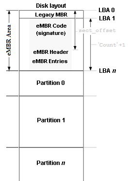
Figure 1: Layout of an eMBR partitioned disk.
Layout
A typical eMBR partitioned media device would contain two or more partitions, each just after the other, all listed in the eMBR headers. At boot time, the eMBR application would load the specified amount of sectors into memory to be able to enumerate the partitions, and display the partitions in a form that the user could choose which partition to boot. The eMBR app would also watch for a key press from the user. If a key press was not found within the specified amount of time, the eMBR app would boot the partition that was most recently booted.
This specification will show the required format and steps to create and boot the eMBR partition scheme and show the format of the partition entries. It is outside this specification on what type of firmware is used to boot from the eMBR partitioned device. If a legacy firmware is used, it is assumed to be a 16-bit Intel® x86 style firmware.
Figure 1 shown to the right, shows a typical layout for an eMBR partitioned disk.
The format of the first few sectors of the disk must follow the outline within this specification. Once the eMBR format is complete, the format of the remaining sectors of the disk is outside this specification.
This specification does not limit the sector size to 512 bytes per sector. However, please note that with the MBR explained below and the offset of the Signature Block within the first sector of the eMBR partitioned area, the sector size is assumed 512. Therefore, if the sector size is more than 512, these offsets remain at the locations as indicated within this specification.
Legacy MBR
The first sector of the disk must contain a Legacy Master Boot Record. The format of this MBR must follow the format originally designed for PC DOS 2.0 in March of 1983. It may contain more modern features but must maintain the standard partition entry table starting at offset 0x01BE. This MBR must contain these four partition entries, with the first one starting at offset 0x01BE, and must contain the standard boot signature at offset 0x01FE, a byte of 0x55 at offset 0x01FE followed by a byte of 0xAA.
The first partition entry must point to the second sector of the disk, LBA 1. This partition table entry must have the values listed in Table 2 below.
uint8_t boot_indicator | This value, when set to 0x80, instructs a legacy firmware that this partition is a bootable partition. For legacy systems, this field must be 0x80. For UEFI systems, this field can be ignored. |
uint8_t start[3] | This is the Legacy CHS value for the start of this partition. This field must be 0x00 (head), 0x02 (sector), 0x00 (cyl) respectively. |
uint8_t sys_indicator | This is the System Indicator. This field must have a value of 0xE0. This is an otherwise unused value that I have chosen for this specification. |
uint8_t end[3] | This is the Legacy CHS value for the end of this partition. This field might be 0xFF, 0xFF, 0xFF respectively, though read a later note for why it may be different. |
uint32_t start_lba | The starting sector of the partition. this field must have a value of 0x00000001. |
uint32_t count | This is the count of sectors used for this eMBR partitioning scheme starting at LBA 1. This field might have a value of 0xFFFFFFFF |
The values in the other three partition entries are not defined within this specification. A driver may use the other three entries to boot other partitions. This specification does not require that the eMBR be the only bootable partition. However, see the notes on "other partitions entries" below.
Please note that it is not a requirement for the Ending CHS and Sector Count fields to be the values defined above. If the disk is not larger than the amount specified, you must use the actual size values to denote the size of the disk. However, if the disk has less than 232 sectors, there would be little reason to use this specification.
Definition of any other part of the Legacy MBR is outside this specification. An implementation may choose to place code within this Legacy MBR to boot one of the included partitions, as long as that partition is within the location and size specifications of a Legacy partition specification. A Legacy boot code must not modify any part of the sectors described within this specification.
eMBR Partition Start
The eMBR partition scheme must start at LBA 1 of the disk. When booted with legacy firmware, within these first few sectors is the code to load the remaining sectors that contain the eMBR Partition Entries, along with the code to display and allow the user to select which partition to boot. This specification limits the amount of sectors reserved for this code and any eMBR partition entries. See the end of this section for information on this limit. When a modern UEFI firmware is used, only the first sector is required, allowing the remaining sectors to be used for entries.
The first sector of the eMBR partition scheme, LBA 1, must contain the following information at offset 0x01F2, shown in Table 3 below. Remember that any code before this offset must jump over this memory block when continuing any (optionally) remaining code.
uint8_t signature[8] | This is the eMBR signature defining this block contains valid values. It must be checked before proceeding. This field must contain the string 'EmbrrbmE' = 0x456D627272626D45. |
uint16_t sect_offset | This is the sector offset to the eMBR Partition Header Block, relative from LBA 0. This limits the count of sectors for the boot code at LBA 1 to 65,534 sectors. This value must be at least 2, leaving one (optionally) used sector for the code and this required Signature Block. See the note below for why this field may be limited. |
uint16_t remaining | This is the count of sectors remaining that must be loaded to include all of the code (not counting this first sector), the eMBR Partition Header, and all of the eMBR Partition Entries that are within the containment of this eMBR partition. A Legacy firmware driver must load these sectors into memory, following the current sector, to be able to read and parse the available entries to display and boot. An UEFI firmware driver must load count = ((remaining + 1) - (sect_offset - 1) + 1) sectors from sect_offset. See the note below for a limit on this field. |
uint16_t legacy_sig | This is the Legacy boot sector signature, 0xAA55, of offset 0x01FE of the sector (in little-endian format). |
The remaining area from LBA 1 to the LBA specified by 1 + remaining, not counting the Signature Block specified above, is for the use of the eMBR driver. If this is a Legacy bootable device, this area must contain all of the code and data needed to parse, display, and boot the desired partition.
It is recommended, but not required, that you include at least one unused sector at the end of this code block for future improvements. It is also recommended that you included a few unused sectors at the end of the partition entry list for future partition entries. i.e.: The sect_offset value be a few more sectors past what is needed for the code and the remaining value be a few more sectors than is needed to hold the current count of partition entries.
An eMBR partitioning scheme partitioned device does not necessarily have to be bootable by legacy firmware. A device can be partitioned using this scheme and booted via modern UEFI firmware. With this in mind, there only needs to be a minimal of one sector present after the MBR and before the sector containing the Partition Header. If this is the case, this sector must contain a minimal amount of 16-bit realmode code to simply display a message and halt if ever it is booted from legacy firmware.
If this partitioned device is legacy firmware bootable, there must be a limit to the count of sectors used for code and sectors used for Partition Entries, so that a 16-bit legacy firmware can access all code and Partition Entries with a single 64k offset. Therefore, for legacy firmware devices, this specification limits the count of remaining sectors used (defined in the remaining member above) times the size of a sector to 64k. In other words, all code and data used must fit within 65,536 bytes starting with the first byte at LBA 1.
Therefore, for Legacy firmware devices, the following statement must be true: ((1 + remaining) * bytes_per_sector) <= 65536, giving a limit of just more than 500 partition entries, depending on the size of the code present to parse them. If legacy firmware code is present, it must check that this limit is adhered to before continuing on.
When a device is booted via modern UEFI firmware, the count of partition entries is only limited by the 16-bit entry_count field below. Therefore, when booting using UEFI firmware, this limit is now at 65,535 entries.
eMBR Partition Header
The eMBR Partition Header will be at the LBA specified in the 16-bit value of sect_offset in the Signature Block detailed in the previous section. This block and all remaining partition entries should have been read into memory with a capable driver outlined in the previous section. The size in bytes of this block containing this eMBR Partition Header and all Partition Entries will be the value in remaining in the Signature Block above, plus 1 for the sector containing the Signature Block, minus sect_offset, then multiple by the size of a sector.
The eMBR Partition Header, detailed below, contains the information needed to know how many partition entries are included, the boot delay time to wait for user input, and a 32-bit checksum to verify validity of the entries. This header is shown in Table 4 below.
uint32_t magic0 | This is the first signature value used to validate this block. It must contain 'EMBR' = 0x52424D45 |
uint32_t checksum | This is the 32-bit checksum of this block plus a count of entry_count entries that follow. When calling a checksum calculation that includes this field, be sure to initially zero this field to get a correct calculation, optionally restoring the value or setting to the new calculated value. See the end of this section for a calculation on the count of bytes to check. |
uint16_t entry_count | This is the count of entries that follow this block. See the next section for the format of an entry. |
uint8_t boot_delay | This is the count in seconds that the driver should delay before automatically choosing the last booted partition. Zero may be used for no delay. However, please note that if there is no delay, the user must use a different form of access to modify the saved delay value. It is recommended that a driver check for a key press before checking the delay value of zero. |
uint8_t version | Version of the specification this partitioning scheme supports. The high 3 bits are the major version, with the lower 5 bits as the minor version. If this document is version 1.05, it would be stored as a byte as 00100101b in binary, 0x25 in hex, or 37 in decimal. Since backward compatibility makes no sense, this value must be no less than 0x25, allowing the minor version to increase since it designates no structural changes. |
uint64_t total_sectors | This is the total count of sectors used by this partitioning scheme. This will be the count of sectors from LBA 0 to the last used sector this eMBR describes. Optionally, if they exist, this can also be used as the LBA of the first sector after all the sectors this eMBR encompasses. |
uint8_t reserved[8] | Reserved and preserved. |
uint32_t magic1 | This is the ending signature value used to validate this block. It must contain 'RBME' = 0x454D4252 |
A driver should verify the two 32-bit signature values along with verifying the 32-bit checksum of this header and the following partition entries. The checksum follows that of the official CRC-32 standard and uses the 0x04C11DB7 Polynomial.
The checksum is done consecutively on this 32-byte block and the amount of memory following, sized by the entry_count field, times the size of a partition entry defined later. If a partition entry is marked invalid, the checksum is still done on that entry. For example, the checksum is done on the memory starting at this Partition Header Block and for the bytes that follow with the length calculated as:
byte count to check = ('size of this header' + (entry_count * 'size of an entry'))
eMBR Partition Entry
All eMBR Partition Entries follow the Partition Header described in the previous section. Each partition entry is 128 bytes in length and contains the format shown in Table 5 below.
uint32_t flags | Flags for this partition: bit 0, when set, is used to indicate that this partition entry is valid and used. bit 1, when set, instructs the driver to hide this partition from a default listing. If bit 1 is set, it should hide any unused (bit 0 = 0) entries as well. All other bits are reserved and must be preserved. |
uint32_t magic | This is a signature to help ensure a valid/used entry. When this entry is used, bit 0 above is set, this must contain 'eMBR' = 0x52424D65. When this entry is not used, bit 0 above is clear, this field must zero. |
uint64_t base_lba | This is the starting sector of this partition relative to the start of the disk. |
uint64_t size | This is the sector count of this partition. |
uint8_t name[64] | This is a null terminated UTF-8 string describing this partition. |
uint64_t created | This is the seconds since 01 Jan 1980 this partition was created. |
uint64_t booted | This is the seconds since 01 Jan 1980 this partition was last booted. If this value is zero, this partition has not yet been booted. |
uint64_t os_signature | This is an 8-byte signature used by the operating system that exists on this partition. The value of this field is not defined by this specification. This field must be preserved by a driver when not in use. |
uint8_t reserved[16] | Reserved and preserved. |
Requirements
It is not required that all partition entries be valid. However, any entry (valid or not) must be at an offset of 128 bytes from the last entry with the first entry following directly after the Partition Header.
A partition must not overlap another partition. Any sector contained within one partition must not be contained within another partition.
The size of a partition does not have to occupy any sectors after that partition and before the next partition. Any sector count between partitions must be considered lost and unusable. This space must not be written to or if read from byte any eMBR driver.
The first partition, the partition with the lowest starting LBA, is not required to start directly after the Partition Entry List.
The booted entry must have its elapsed time updated to the current elapsed seconds since the Epoch date specified within this specification just before the driver transfers control to the loaded partition. Other than this item, it is outside this specification on whether the remaining values within the partition entry and Partition Header are modified. However, please note that when you modify an entry, you must update the checksum in the Partition Header.
It is outside this specification on how a user adds, deletes, or modifies a Partition Entry, as long as the resulting modification follows the format listed within this specification.
All LBA's used within this specification, unless otherwise noted, are relative to the start of the disk, LBA 0.
A combined value of a partition's base_lba and size must not exceed 264-1 sectors.
Any of the other three partition entries in the Legacy MBR at LBA 0 may point to any partitions within the eMBR scheme with the restriction that any of these partitions must reside within the 232-1 count of sectors from the start of the disk. Any non-eMBR driver must not modify any of the sectors from LBA 1 to LBA 1 + remaining.
The volume boot record residing at the first sector of any partition must not assume that it was initiated by an eMBR loader. It must parse the disk or use an alternative procedure to determine where it is located, and any procedure to do so is outside this specification.
User interface
It is outside of this specification on how the user interfaces with the driver or how the driver displays the list of partitions. It is suggested that a list be shown similar to Figure 2 shown here. This is an example of a Legacy firmware booted disk.
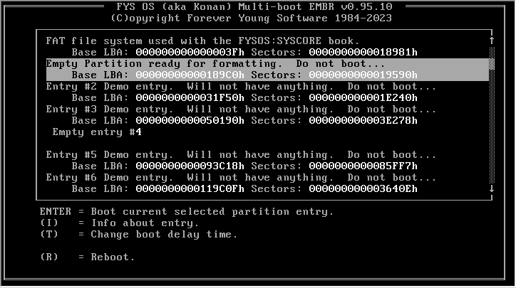
Figure 2: Suggested User Interface.
It is suggested that at the first point of user intervention (a key press) that the countdown to boot be stopped and the interface wait for the user to continue. It is also suggested that the driver allow the user to adjust the countdown time for future boots.
It is suggested that the user be able to indicate to the driver to display and possibly edit the OS Signature Block within the Partition Entry.
Please see the code listed in the downloads section for a good example of a legacy firmware booted app that follows this specification when listing and booting the included partitions.
Things to consider
Since this technique of disk partitioning allows for much larger disk sizes than what was previously available, you will need to take the following notes into consideration.
- FAT file systems: Since the FAT file system contains a "hidden sectors" field in the BIOS Parameter Block, indicating how far away from the start of the disk this file system resides, take into account that this BPB field is only 32-bits in size. Therefore, you may not be able to boot from this partition, and depending on how your file system driver is configured, you may or may not be able to read from this partition, if this partition is located beyond this 32-bit LBA size.
- All systems: Depending on your platform, you will need to have 64-bit unsigned integer storage to use this technique of disk partitioning if you have more than 0xFFFFFFFF (4,294,967,295d) sectors.